Difference between revisions of "Kerbal to Pro: Modelling in 3ds Max"
Bilsta1000 (talk | contribs) (→Foreward) |
Bilsta1000 (talk | contribs) (→Foreward) |
||
| Line 18: | Line 18: | ||
Because of this I have made this tutorial to be friendly to all skill levels, Brand newbies can follow step by step from actually getting Max to getting their models into unity, | Because of this I have made this tutorial to be friendly to all skill levels, Brand newbies can follow step by step from actually getting Max to getting their models into unity, | ||
| + | |||
meanwhile advanced modellers can click straight through to helpful sections such as setting up Max for KSP. | meanwhile advanced modellers can click straight through to helpful sections such as setting up Max for KSP. | ||
Revision as of 15:45, 11 June 2013
Contents
Foreward
By Bilsta1000. This tutorial will cover creating the geometry, texture and animation for a MIR Docking Port.
It will also include getting your model into KSP using unity and how to set up your collision meshes correctly.
Please bear in mind this is a work in progress so chapters will be completed as and when I have free time to continue. (I have a life outside of KSP)
Message from the Author:
A bit of background to me: I’m a final year university student who has been using Max, Maya and various other pieces of 3d modelling software on and off for several years.
Having been taught myself and also being taught by professionals and amateurs alike, I know how intimidating and confusing some pieces of software can be to work with.
Because of this I have made this tutorial to be friendly to all skill levels, Brand newbies can follow step by step from actually getting Max to getting their models into unity,
meanwhile advanced modellers can click straight through to helpful sections such as setting up Max for KSP.
if you decide to use this tutorial, I have one simple request:
Please don’t follow this tutorial to the dot; I’ve intentionally left out steps to make sure that following my every single mouse click is very difficult.
This way, rather than learning to model a MIR Docking Port, you’ll learn to create whatever it is you’d like to create.
Contents
Chapter 1: Acquisition
If you’re a student then you can download free versions and get free licences for Max, Maya and any of the Autodesk suite.
All you have to do is register at http://students.autodesk.com/ and scan or take a photo of your student card.
In this tutorial I'll be working with 3ds Max 2014
Chapter 2: Familiarisation
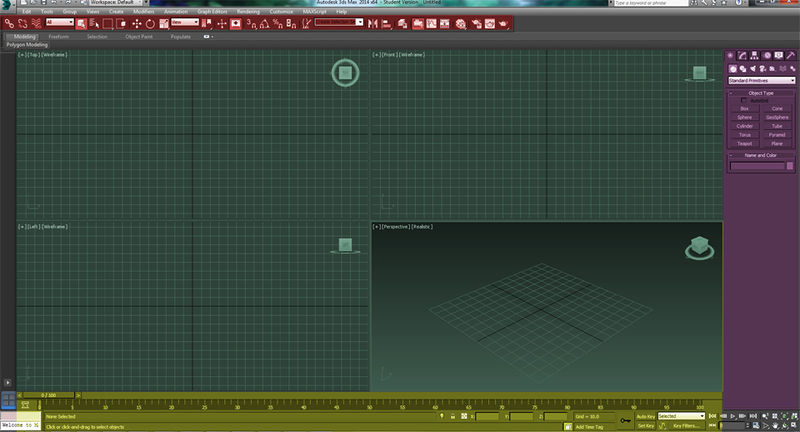
Max can be very intimidating on first launch, especially if you've never used it before. So first we will get used to where everything is.
Viewports
First you have your viewports (green) where your model will sit whilst you edit it. Any of the views can be edited if for example you'd like a textured view in one and a flat wireframe in another. It's your Max, Have it your way.
It's also possible to maximize one of these views so that it takes up the whole screen by pressing ALT + W
By default navigating this view is done with the mouse, here are some very useful notes on navigation alone.
- Left mouse button - Select
- CTRL + Left mouse button - Add to selection (Also works with click and drag)
- ALT + Left mouse button - Remove from selection (Also works with click and drag)
- Middle Mouse button (Click the scroll wheel) - Pan around view
- CTRL + Middle mouse button - Pan around view faster
- ALT + Middle mouse button - Orbit around view
- CTRL + ALT + Middle mouse button - Zoom in and out
- Right mouse button - Context menu
- CTRL + Right mouse button - Quick access menu (New objects and transforms)
- SHIFT + Right mouse button - Quick access menu (options)
- ALT + Right mouse button - Quick access menu (pivot point options)
Toolbars
The toolbars (red) contain the controls you need to manipulate your models. from left to right (default) they go
- Select and link - use for parenting
- Unlink Selection - use for unparenting
- Bind to spacewarp - (Never used it myself)*
- Selection filter - when selecting an object, you can only select what's in this box.
- Select object - Select objects using your mouse
- Select by name - Opens a window where you can select an object by name, Usefull if you have a lot of parts to your model.
- Selection region (hold) - With this you can change how you click and drag to select objects.
- Window/Crossing - Which parts are included in your selection
- If set to Crossing, whilst clicking and dragging, if any part of the geometry is dragged over it will be included in the selection.
- If set to Window, whilst clicking and dragging, the entire part needs to be inside the bounding box for it to be included in the selection.
- Select and Move - Select an object and moves it around (Shortcut: CTRL + W)
- Select and Rotate - Select an object and rotate it around (Shortcut: CTRL + E)
- Select and Scale - Select an object and scale it up or down. (Shortcut: Ctrl + R)
- Refference coordinate system - This changes the orientation of your transform gizmo for when you manipulate your objects.
- View - The default, The gizmo will be paralell with the viewports grid.
- Screen - The gizmo will be paralell with your computer monitor
- World - Usually the same as the viewport unless you have changed the orientation of your grid.
- Parent - (Never used it)
- Local - (Never used it)
- Gimbal - (Never used it)
- Grid - The gizmo will be paralell with the grid.
- Working - (Never used it)
- Pick - (Never used it)
- Change pivot point - This has quick options to move your pivot point around, Bear in mind you can move your pivot point anywhere you want by using the Heirachy panel.
- Use Pivot Point Center - This is the default location or where you have moved it using the Heirachy Panel
- Use Bounding Box Center - This moves your pivot point to the center of the bounding box.
- Use Transform Coordinate Center - Moves your pivot point to (0,0,0)
These are most of the tools you'll need, I find it easier to relax my left hand on the W + E + R keys which then makes "Move" my ring finger, "Rotate" my middle and "Scale" my index.
The Panels
Usually found on the right hand side of the screen, the panels window (Purple) is used for any creation or editing to your model.
It has six sections.
- Create - Add something to your scene
- Modify - Modify something in your scene.
- Heirachy - Modify any parenting or scene options such as the Pivot Point
- Motion - Used for Mocap and controlled animation.
- Display - Used to show and hide parts of your scene.
- Utilities - Helpfull little scripts.
I will go into more detail into certain sections of this as and when we need them as there is way too much to cover.
The Timeline
This will be covered in the animation section, for basic modelling you don't need this.
WHY CAN'T I SELECT ANYTHING
When I first started out using Max, I found it to be very confusing whenI tried to do something and something other than what was expected happenedinstead. Because of that here are Bilsta’s helpful solutions to the problem of “Ican’t select my object”
- You have object select locked…. Press [Spacebar].
- In Wireframe view, You're attempting to select the object itself rather than the wireframe.
- You’re trying to create something; you probably have a button in the [Create] menu clicked. Try right clicking a few times or pressing [Escape]
- Your object is frozen, Right click and click [Unfreeze All]
- You’re in subselection mode – When this is the case you can only select whichever subobject you have selected. Eg. Vertices or Edges, Turn it off in the [Modifiers] stack
- You’re making a crossing selection when your [Window/Crossing] toggle is set to window. See the section above on toolbars.
Chapter 3: Research
When modelling a part, the most important step is to have some sort of refference material.
This can be anything you can get your hands on whether it be three-views, images, videos, whatever, just have a lot of it. I usually dedicate a folder to the object in question and put all of the photos in there, then I can just flick through when I need to know something. For this tutorial I will be modelling the MIR Docking port as it's a pretty basic model to start with.
I've found some photos and they're all ready to be flicked through when I need to know something.
I've found a blueprint kind of view which will come in very handy when it comes to modelling.
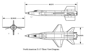
Three Views
Correct-scale three view images are the holy grail of modelling research, if you have one of these, then you can at least model the geometry very closely to correctly
Images
Images can give you overall ideas of how the texture and geometry all fits together.
Video
Videos are brilliant for animation
Chapter 4: Setting up Max
Firstly we need to make sure that the Max units are equal to 1 Unit = 1 Meter.
This is done by going to Customise --> Units Setup.
I'm setting my unit scale to Metric and in [System Unit Setup] I actually set how much one unit is equal to.
I will probably only need a side view for now to get the basic shape and then later when it comes to detailing I'll use the rest of the research.
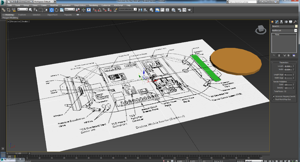
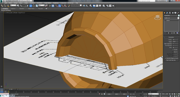
I create a plane by going to the [CREATE] Panel and selecting [Plane], I then click and drag on the grid to create it. This will have the side view image so I can model off it easier.
To then add the image I need to give this plane a material; I go to [Rendering] --> [Material Editor] --> [Compact Material Editor].
Once the Material editor has opened I find the Diffuse colour which is a basic object texture. Next to diffuse there is a gray box (by default) this is the colour of that particular material. Next to that gray box is another darker gray box which is for your maps. For this we will use a BITMAP so I click on the gray box next to the lighter gray box and then select [BITMAP]. This then opens my file explorer, I find the image and it is applied to the material.
Now we need to assign that material to our geometry; I click and drag the material from the material editor onto my plane.
By default the image will not be displayed on the geometry, You have to click on your viewport render style which is next to the viewport name (Left, Top, Perspective), go down to [Materials] and click either [Shaded materials with maps] or [Realistic materials with maps] depending on whether you want it quickly rendered in your viewport (shaded) or realistically rendered in the viewport. If you experience lag, this is the first thing to change.
Once there's a nice refference in our viewport we can make sure it's scaled right. If you have access to technical details this can aid you quite a bit but bear in mind you need to scale relative so that the object is then useful in KSP. For example this Docking Module is 2.6M diameter x 4.7M length so these wouldn't be very useful if you tried to dock to it with the stock parts.
This module will be designed to fit on 2m radial pieces so firstly I created a cuboid that is 4m length, (remember radius is only the size to the center) and lined my plain up with it to make sure that the scale was correct.
Chapter 5: Modelling
Firstly I created a 2m cylinder since this is the sort of shape the end result kind of looks like.
I positioned it over the part where the docking port will be and rotated it so this will definitely fit on a 2m part.
I delete the two ends so that I have a hollow cylinder and I work from that.
At the bottom there is three numbers labeled X Y Z, these are absolute values hence if you set a parameter to 0 then we know it's centered as I have with the Z and Y axis.
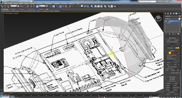
Once it's all centered I add an [Edit Poly] modifier by clicking on the [MODIFIER LIST] on the right hand side. This means that we can now edit the subgeometry (Vertices, edges and faces).
Once my first piece is in the right place. I then Extrude the geometry by holding [SHIFT] whilst I [Move], [Rotate] or [Scale] and work my way across using the image as a guide only scaling on the Y/Z axis as I go. I find it useful to model with my camera on an angle whilst keeping the center of the geometry central on the design. Then if I need to refference how curvy it needs to be I can see that
A good shortcut key at this point is [ALT] + [X] this will make the piece of geometry selected transparent so you can work on it easier.
Once I've reached the end, I pull the geometry all the way in and apply a [CAP ENDS] Modifier to seal it closed, There are other ways to do this but I find a cap ends modifier is the easiest and best way.
So now that our main shell is complete. I start to model the two solar arrays. Because there's no end view of these I'll have to just match the refference images
