Difference between revisions of "Tutorial:Learning basics of rocket building"
| Line 36: | Line 36: | ||
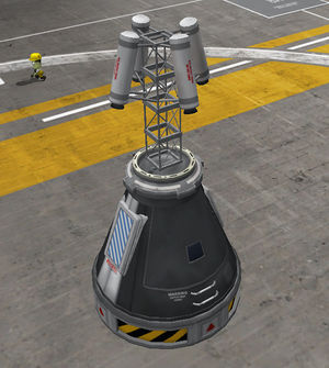
[[File:Cabin-Decoupler.jpg|center|thumb|The ready escape cabin with the decoupler ring]] | [[File:Cabin-Decoupler.jpg|center|thumb|The ready escape cabin with the decoupler ring]] | ||
For the proper working of the escape cabin it has to be separated and leave the rest of the rocket behind. | For the proper working of the escape cabin it has to be separated and leave the rest of the rocket behind. | ||
| + | For separation, and generally for sectionalizing of the rockets (and any other types of craft too) we can select from three family of parts: | ||
| + | *'''[[Docking/hu#Docking ports|Docking ports]]''': | ||
| + | :They make the flow of [[resource]]s free - what can sometimes quite a disturbing, and if we want to deny the flow trough these ports for reserving the upper stage reserves, the the fuel transfer can be prohibited at [[launch]] (using '''''Disable Crossfeed''''' [[tweakable]]), somehow it is not possible in the editor. Using two proper pieces make the docking possible too. But these connections are not so rigid and less chargeable, because of this only smaller units can placed on them. They don't works by [[stage|staging]], their ejection force is low (the changing of impulse pushes the two section away from each other). Although a such connection can be staging - by placing a separator between the doors. | ||
| + | *'''[[Decoupler]]s''': | ||
| + | :The propellants cannot pass these parts, so if we need something like this we have to use [[FTX-2 External Fuel Duct]]s. It also creates a fairing for the [[engine]]s placed beneath. After the decoupled form the section indicated by the arrow the reconnection is not possible. There are radially attachable variants in this family too! | ||
| + | *'''Separators''': | ||
| + | :Works similarly to decouplers. They release both side, somewhat heavier and have greater ejection force. | ||
| + | |||
| + | As you see, an [[TR-18A Stack Decoupler]] was chosen, and the arrow points towards the cabin, meaning the separation happens under the cabin. Even a [[TR-18D Stack Separator]] satisfies the requirements. Everybody can place here what fits for his taste. | ||
| + | |||
| + | <span id="action groups"></span> | ||
| + | ==== Setting off the action groups ==== | ||
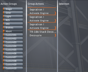
| + | The [[action group]]s make the execution of several actions of several parts placed in an action group by a single keystroke. These groups can be divided into two types: basic and custom. In case of basic action groups we can attach more action to an already existing default actions, meaning we can assign an [[electric light]] to the barking group, and the selected illuminator will light up at braking the [[rover|wheels]]. These groups are the '''''Stage''''' ({{Key press|Szóköz}}), the '''''Gear''''' ({{Key press|G}}), the '''''Light''''' ({{Key press|U}}), the '''''RCS''''' ({{Key press|G}}), the '''''SAS''''' ({{Key press|T}}), the '''''Brakes''''' ({{Key press|B}}), and the '''''Abort''''' ({{Key press|Backspace}}). The custom groups have no default effects, and can be operated by the equivalent keys of {{Key press|1|2|3|4|5|6|7|8|9|0|chain=}}. | ||
| + | [[File:Cabin-AG-Abort.png|thumb|center|The setting of emergency escape]] | ||
| + | {{clear}} | ||
| + | [[File:action group icon.png|left|link=]] | ||
Revision as of 17:18, 8 April 2015
For doing this tutorial start a game in sandbox mode, and enter into the Vehicle Assembly Building in the KSC.
The first step of the rocket building is defining the purpose of the rocket, because this purpose determines the terminal stages act as payloads, which size and weight and destination determines the requirement of interplanetary and middle stages, and finally the total weight of these stages hedges in the parameters of the possible launch vehicles. As a result of this, the most practical way of constructing the rocket is starting with the final stage(s), and build it from up to down.
Contents
The controlling part of the rocket - and the functions of the editor
The proper command module
The command module practically placed on the final stage, because such a way it can control the craft from the launch till the end during the mission. For the manned missions cabins holding kerbonaut(s) are needed. For a mission needs a single kerbonaut a Command Pod Mk1 is enough, but if we want to make a mission with full crew (pilot, engineer and scientist), an Mk1-2 Command Pod is necessary. The presence of an experienced pilot can be compensated with installation of a proper probe core. For the manned missions the return of the crew has to be ensured, so if there is no a separate vehicle for bringing our heroic kerbonauts back to Kerbin, this stage has to be functional as a returning unit. For launching a radically new rocket not tested yet, avoiding the loss of kerbonauts a Launch Escape System (LES) has to be installed on the cabin too.
If the rocket's role is delivering a remote craft, that craft's probe core can control the whole rocket. If the payload would has no a probe core (refueling unit), then a it has to be built in the final stage of the basic construction.
The crafting of cabins' stage - and what the editor gizmos for
Well, let see the building of a cabin equipped with a LES. There is a proper sized Launch Escape System as a special part for the big cabin fitting on 2.5m rockets, but we have to compose a such device for Mk1 cabin. Now, lets build this module, just for learning.
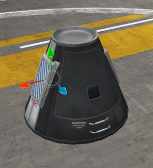
We have to start with placing the command module. Switch the mode control - if it is not in this state - to Parts mode, and change the bar's page to Pods (first from uspide), and select the Mk1-2 Command Pod, and place it somewhere in the workshop. As it has been done the icons of the editor gizmos appear. The sorting preference of the parts can be changed by clicking on the labels of Name, Mass, Cost and Size situated on the top of the parts' bar.
The Launch escape system has to be placed on the top of the cabin, where the parachute used to, such as the Mk16 Parachute with its 0.625m radial size fits perfectly on Mk1 cabin, or Mk16-XL Parachute and Mk25 Parachute (1.25m) fits on the Mk1-2. In this case, an group of Mk2-R Radial-Mount Parachutes must placed on the surface of the cabin symmetrically. The situation is similar when docking ports is installed on the top for availability of the docking later. Due to the launch escape system means unnecessary extra weight during the spaceflight, it worth to decouple after the initial sequence of ascending - so it has to be installed on a decoupler, separator, or a kind of the mentioned docking ports.
For the radially symmetric placement switch the symmetry indicator to radial symmetry position, if it is in lateral symmetry mode. Switching is possible between these modes by pressing R, the number of the symmetrically placed parts can be increased by clicking on the indicator or pressing X, an decreased by right-clicking on the indicator or pressing ⇧ Shift+X. Lets place two Mk2-R Radial-Mount Parachute (Utility group in the parts' bar) in radial symmetry on the cabin.
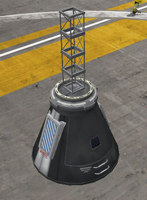
If the parachutes are positioned on the most ideal place possible, it is the high time to start to construct the escape tower. Switch the gizmos to Place state (clicking on the first icon from left, or press 1). The state of symmetry mode doesn't affect anything when we are building on the symmetry axis. If we need a docking port for the later fuel transfers, then a Clamp-O-Tron Jr. is the proper part for us, else a TR-2V Stack Decoupler can be a perfect base too. So put one of them on the top of the cabin. Stack four Cubic Octagonal Strut for creating a platform for the boosters placing enough distant from the cabin preventing any damage.
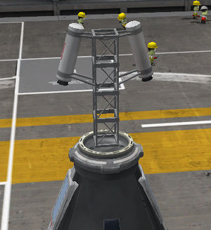
As the tower is ready, the boosters have to placed on it. Due to sizes of the available boosters, the Sepratron I is the only candidate to imagine. To place them in right way the role of the tower must be understood. At first it has to accelerate together with the cabin like the rest of the rocket, and during the acceleration it diverts from the course of the rest of the rocket, and it lifts the cabin to safe altitude to open the chutes. The cabin has to accelerate at least with 5 g. This - and the weight of the cabin - determinates the number of the boosters. But worth to know, installation of each booster increases the empty weight, even if for a short time. For more accurate placement switch on the Angle Snap clicking on its icon, or pressing C. In switched on state, the icon has a hexagon state, and a circle, if switched off. Put a pair of Sepratron symmetrically on the top of the tower - but such a way, that their jet of flame evade the surface of the cabin. Hold down the ⇧ Shift and push S 3-4 times (without holding down the ⇧ Shift, the rotation angle would be 90°, instead of 5°) to achieve this. To rotate to the opposite direction just press W - and hold down the ⇧ Shift for smoother scales.
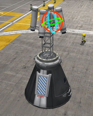
Now turn off the symmetry (technically decrease to one), and place one-one rocket on the opposite side of the tower "symmetrically". These two boosters have to be almost symmetrical. And here the almost is important! If we had placed these "symmetrically", but definitely not in symmetry mode - because in symmetry mode each modification also affects the symmetrically placed parts - turn the Rotate state on. This is the third icon among the editor gizmos, or a simple keystroke: 3. In this state we can tweak the part's orientation without breaking the connection - similarly to the 'offset' mode. To ensure the minor asymmetry lets ruin the orientation of one of these boosters, most practically catching and dragging the red ring. The holding down the ⇧ Shift means smoother scales of modification. The effect of this gizmo mode is same as the usage of WSADQE keys at placement.
For the proper working of the escape cabin it has to be separated and leave the rest of the rocket behind. For separation, and generally for sectionalizing of the rockets (and any other types of craft too) we can select from three family of parts:
- They make the flow of resources free - what can sometimes quite a disturbing, and if we want to deny the flow trough these ports for reserving the upper stage reserves, the the fuel transfer can be prohibited at launch (using Disable Crossfeed tweakable), somehow it is not possible in the editor. Using two proper pieces make the docking possible too. But these connections are not so rigid and less chargeable, because of this only smaller units can placed on them. They don't works by staging, their ejection force is low (the changing of impulse pushes the two section away from each other). Although a such connection can be staging - by placing a separator between the doors.
- The propellants cannot pass these parts, so if we need something like this we have to use FTX-2 External Fuel Ducts. It also creates a fairing for the engines placed beneath. After the decoupled form the section indicated by the arrow the reconnection is not possible. There are radially attachable variants in this family too!
- Separators:
- Works similarly to decouplers. They release both side, somewhat heavier and have greater ejection force.
As you see, an TR-18A Stack Decoupler was chosen, and the arrow points towards the cabin, meaning the separation happens under the cabin. Even a TR-18D Stack Separator satisfies the requirements. Everybody can place here what fits for his taste.
Setting off the action groups
The action groups make the execution of several actions of several parts placed in an action group by a single keystroke. These groups can be divided into two types: basic and custom. In case of basic action groups we can attach more action to an already existing default actions, meaning we can assign an electric light to the barking group, and the selected illuminator will light up at braking the wheels. These groups are the Stage (Szóköz), the Gear (G), the Light (U), the RCS (G), the SAS (T), the Brakes (B), and the Abort (⌫ Backspace). The custom groups have no default effects, and can be operated by the equivalent keys of 1234567890.
