Tutorial:Learning basics of rocket building
To start this tutorial, start a game in sandbox mode, and enter the Vehicle Assembly Building in the KSC.
The first step in building a rocket is defining the purpose of the rocket, because this purpose determines how the terminal stages act as payloads, whose size and weight and destination determines the requirements of the other stages, and finally the total weight of these stages determines parameters of the possible launch vehicles. As a result of this, the most practical way of constructing the rocket is starting with the upper stage(s), and building it from top to bottom.
Contents
- 1 The command pod and the functions of the editor
- 2 The typical payloads - and the common systems of the craft
- 2.1 The propulsion
- 2.2 Stabilizers (SAS) and energy generators
- 2.3 The reaction control system (RCS) and the docking devices
- 2.4 Lamps
- 2.5 The devices for landing - landing legs, ladders
- 2.6 Parachutes, and everything else worth to use in the atmosphere
- 2.7 And some parts can be required
- 2.8 And some phrase about the re-usability
- 3 The construction of launch vehicles
The command pod and the functions of the editor
The proper command module
The command module should be placed on the final stage, in such a way it can control the craft from the launch till the end of the mission, and ensure augmented stabilization control. For the manned missions, cabins holding kerbonaut(s) are needed. For a mission that only needs a single kerbonaut, a Command Pod Mk1 is enough, but if we want to make a mission with full crew (pilot, engineer and scientist), a Mk1-3 Command Pod is necessary. The presence of an experienced pilot can be compensated with installation of a proper probe core. For the manned missions the crew should be able to return unless its a "colonization" mission, so if there is no a separate vehicle for bringing our heroic kerbonauts back to Kerbin, this stage has to function as a returning unit. When launching a radically new rocket that has not been tested yet, a Launch Escape System (LES) should be installed on the cabin to avoid the loss of kerbonauts.
If the rocket's role is to deliver a remote craft, that craft's probe core can control the whole rocket. If the payload would not have a probe core (refueling unit), then it has to be built in the final stage of the basic construction.
The creation of cabins' stage - and what the editor gizmos are for
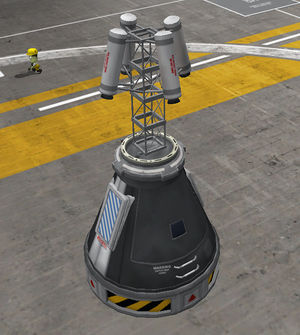
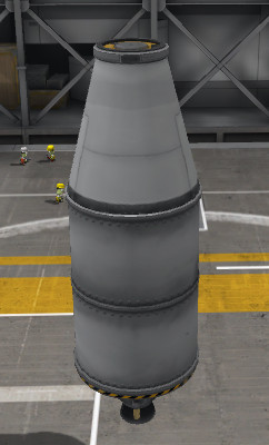
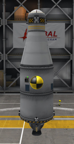
Well let's build a cabin equipped with a LES. There is a proper sized Launch Escape System as a special part for the big cabin fitting on 1.25m nodes, but we have to create one for a .625m node. Now, let’s build this module, just for learning.
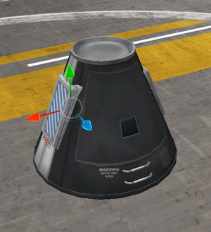
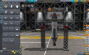
We have to start by placing the command module. Switch the mode control if it isn't already to Parts mode, and change the bar's page to Pods (first from top), and select the Mk1-2 Command Pod, and place it somewhere in the VAB. Once this has been done the the editor gizmos appear. The sorting preference of the parts can be changed by clicking on the labels of Name, Mass, Cost and Size situated on top of the parts bar.
The Launch escape system has to be placed on the top of the cabin, where the parachute usually goes. In this case, a group of Mk2-R Radial-Mount Parachutes must be placed on the surface of the cabin symmetrically to prevent the capsule from hitting the ground too hard. The situation is similar to when docking ports are installed on the top for docking later. Due to the fact that the launch escape system is useless mass during the rest of the flight, it is good to decouple it after the ascent sequence. This means it has to be installed on a decoupler, separator, or some kind of the mentioned docking ports.
For the radially symmetric placement switch the symmetry indicator to radial symmetry position if it is in lateral symmetry mode. Do this by pressing R. The number of the symmetrically placed parts can be increased by clicking on the indicator or pressing X, and decreased by right-clicking on the indicator or pressing ⇧ Shift+X. Let's place two Mk2-R Radial-Mount Parachute (Utility group in the parts bar) in radial symmetry on the cabin.
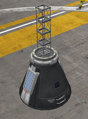
If the parachutes are positioned in the most ideal place possible, it is time to start constructing the escape tower. Switch the gizmos to Place state (clicking on the first icon from left, or press 1). The state of symmetry mode doesn't affect anything when we are building on the symmetry axis. If we need a docking port for the later fuel transfer, then a Clamp-O-Tron Jr. instead of a TR-2V Stack Decoupler can be a perfect base too. So put one of them on the top of the cabin. Stack four Cubic Octagonal Struts to create a platform for the boosters, placing enough distance from the cabin to prevent any damage. If you surely put the on the attachment point (instead of surface), the hold the Mod key pressed during the placement. (the modifier, depending on your OS → Windows: ⎇ Alt; Mac OS: ⌥ Option; Linux: ⇧ Right Shift or ⌘ Win). If you do not want to move your back to the part bar, just hold down the Mod and click on the part (or group of parts) you want to copy.
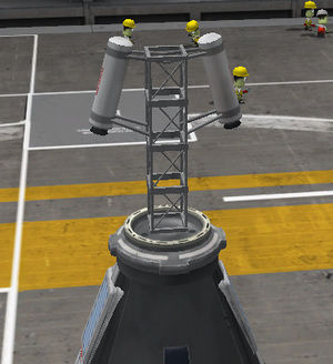
As the tower is ready, the boosters have to be placed on it. Due to sizes of the available boosters, the Sepratron I is the only candidate. To place them in right way, the role of the tower must be understood. At first, it has to accelerate together with the cabin like the rest of the rocket. During the acceleration it diverts from the course of the rest of the rocket, and it lifts the cabin to safe altitude to open the chutes. The cabin has to accelerate at least with 5 g. This - and the weight of the cabin - determines the number of the boosters. But it is worth to know that installation of each booster increases the empty weight, even if for a short time. For more accurate placement, switch on the Angle Snap by clicking on its icon, or pressing C. In its switched on state, the icon has a hexagon state, and a circle, if switched off. Put a pair of Sepratrons symmetrically on the top of the tower but in such a way that their jet of flame evades the surface of the cabin. Hold down the ⇧ Shift and push S 3-4 times (without holding down the ⇧ Shift, the rotation angle would be 90°, instead of 5°) to achieve this. To rotate to the opposite direction just press W and hold down the ⇧ Shift for smoother scales. For resetting the orientation just push the space.
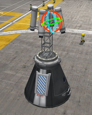
Now turn off the symmetry (technically decrease to one), and place one-one rocket on the opposite side of the tower "symmetrically". These two boosters have to be almost symmetrical. And here the almost is important! This is because in symmetry mode, changing one part affects the one on the opposite side. To start, enable the rotation gizmo. This is the third icon among the editor gizmos, or a simple keystroke: 3. In this state we can tweak the part's orientation without breaking the connection - similar to the 'offset' mode. To ensure the minor asymmetry, let's ruin the orientation of one of these boosters, most practically catching and dragging the red ring. Holding down the ⇧ Shift means smoother scales of modification. The effect of this gizmo mode is same as the usage of WSADQE keys at placement.
For the escape pod to properly work, it has to be separated and leave the rest of the rocket behind. For separation, and generally for sectioning of the rockets (and any other types of craft too) we can select from three families of parts:
- They make the flow of resources free - which can sometimes be quite problematic, and if we want to disable the flow through these ports for [reserving the upper stage reserves, the fuel transfer can be prohibited at launch (using Disable Crossfeed tweakable) (somehow it is not possible in the editor). With two docking ports of the same diameter one can dock ships, useful for landers and space stations. These connections are not very rigid. They don't work by staging (but can do so by setting to Port: Enable Staging, but sincerelly not recomended as the staging icon will remain on the stagingbar after the action), their ejection force is low (the changing of impulse pushes the two section away from each other).
- The fuel cannot pass these parts (yes, also can be tweaked: Enable Crossfeed), so if we need something like a drop tank we have to use FTX-2 External Fuel Ducts. It also creates a fairing for the engines placed beneath. After the decoupled form the section indicated by the arrow reconnection is not possible. There are radially attachable variants in this family too!
- Separators:
- Work similarly to decouplers. They release both sides, are somewhat heavier and have greater ejection force.
As you see, an TR-18A Stack Decoupler was chosen, and the arrow points towards the cabin, meaning the separation happens under the cabin. Even a TR-18D Stack Separator satisfies the requirements. Everybody can place here what fits for his taste.
Setting off the action groups
The action groups make the execution of several actions of several parts placed in an action group by a single keystroke. These groups can be divided into two types: basic and custom. In case of basic action groups we can attach more action to an already existing default actions, meaning we can assign an electric light to the barking group, and the selected illuminator will light up at braking the wheels. These groups are the Stage (Space), the Gear (G), the Light (U), the RCS (G), the SAS (T), the Brakes (B), and the Abort (⌫ Backspace). The custom groups have no default effects, and can be operated by the equivalent keys of 1234567890.
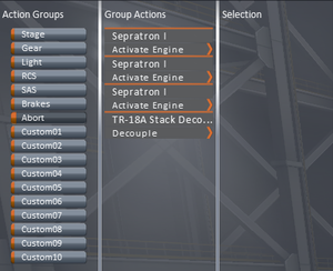
For setting the action groups at first change the editor mode to Action Groups by clicking on its icon along the top. There is a "Abort" group in the list, well suited for the purpose of our escape cabin. Let’s choose it. That means activation of the boosters and decoupling the cabin need to be in this group. At first choose the desired part by clicking on it, in this case the Sepratron I. Once that is done, the options of the selected part appears in the Selection column, and the selected part start to glow in a greenish light. To make the booster start using action group select the Activate Engine option. Good to know: it is possible to give several actions to a single part in an action group, and each action group setting is applied to the symmetrical parts too. There is a Reset button for undoing the settings. The actions already set off for the given action group are shown in the Group Actions column. In this column the part can be selected by clicking, and the action(s) can be removed by clicking on the given action. Now, give the activation for the remaining Sepratron Is, and the decoupling of the decoupler ring (Decouple).
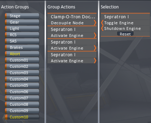
We have to do something similar for decoupling the LES: activating the Sepratron I boosters, and decoupling from the docking ports (Decouple Node). If a part has role in several action groups, the names of the overlapping action groups turn yellow. As the separation of the tower doesn't connect to any basic action group, it is better to use one of the custom action groups. The 10th custom action group (Custom10) is selected in the picture, can be activated by pressing the 0.
The parachutes can be controlled by action groups also. If the 1st custom action group and set the chutes' Deploy custom, then the chutes will be deployed by pressing the 1.
Selecting the members of the crew
The third icon in the row is the Crew, gives opportunity to selecting the members of the crew. The kerbonauts have different properties - although these features works only in career game mode. The pilots are able to control the craft more efficiently using the craft's Stability Augmentation System, the engineers are able to repair craft that others are not, and the scientist are the experts of scientific activity. Naturally, installing a probe core allows different Stability Augmentation System settings according to the capability of the probe core - and remains controlable even without any crew.
The available kerbonauts can be placed any available seat in the menu of crew, but these changes don't get saved. This worth to set up only just before the launch.
Let’s try it!
The "launch" makes something come to mind: if all these things are done, we can test the escape cabin. Let’s click on the Launch icon on the top right corner. This moves the vehicle onto the launch pad. We can test the cabin here. For testing the decoupling of the tower from the cabin just press 0. At this moment if you have done everything right the boosters on the tower activate, the truss of the tower is released from the cabin, and vanishes in the sky. For another test press ⎋ Esc, and in the appearing Game Paused window choose after the Revert Flight the Revert to Launch option.
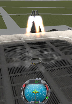
The emergency decoupling is testable too. Once the ⌫ Backspace is pressed, the boosters on the tower pull the cabin from the ring, and due to the minor asymmetry the cabin won't ascend vertically but drift away from the starting point. Once the cabin has reached a safe altitude the tower must be decoupled by pressing 0, as the cabin starts to fall the parachutes have to be deployed by pressing 1 button. After a successful test the cabin with the "rescued" kerbonaut lands safely on the grass nearby the launch pad.
Staging
There are quite a few action groups and they must be memorized, but the stages can take the actions by only pressing the Space, although only by the preprogrammed sequence. The staging ha a serious limit - only one certain action of certain parts can be activated by this method, and only once. There is a Stage action group, but it like the other action groups work at each keystroke (in this case: Space), and cannot leash to a definite staging icon. However the staging sequences can be changed during missions.
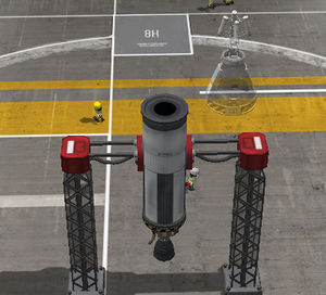
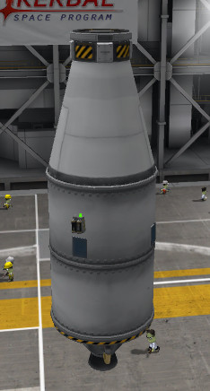
For switching the the craft by staging during the during the whole launch, the docking port on the top of the cabin has to be changed to an TR-2V decoupler ring (attend to its direction, and do not forget to add it to the Abort action group). Well, it is the time to test the escape capsule on a working rocket. Let’s install an FL-T800 Fuel Tank under the capsule, and an LV-T45 Liquid Fuel Engine under the tank. Attach a pair of TT18-A Launch Stability Enhancer symmetrically on the tank as in the picture.
If all of these are finished, then setting up the staging is the next. The actions done during the successful have to be thought about before sorting the staging icons (the emergency scenario is done by the “Abort” action group fitting to this):
- Activating the rocket engine
- Releasing the launch stability enhancers
- Jettisoning the escape tower
- Decoupling the cabin
- Deploying the chutes
Because the rocket engines are able to run at peak output at the moment of activation, the first two steps can be merged - but when jet engines are used, since they need time to reach their maximal output this merging is not practical. The decoupler rings and the rocket engines above them can be merged in a single staging folder.
The staging icons can be resorted by click and drag method in the staging bar, click them, and if the parts they represent are placed in symmetry, it will expand. The selected parts glow greenish light. Use the left-^ Ctrl and left mouse button click to select multiple icons, and drag them into the desired stage. The “+” mark gives new folder, and the “-” can delete the empty folders. The Reset button on the bottom of the staging bar erase and recreate (so and so usable) the staging automatically.
Setting the tweakables
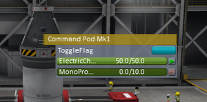
Many parts have tweakable parameters. To change the parameters just right-click on the selected part.
Try it with the Command Pod Mk1. In the popping up window the ToggleFlag gives option of the presence of the mission's flag. The bars below give us the opportunity to edit the amount of the resources. Now the monopropellant is useless without rcs, and increases the mass, so set its amount to zero. The switches on the right of the bars adjust the open and closed state of the container. Of course, the tweakables change by the parts, and some of them work during the missions, so the closed tanks can be kept as an emergency reserve.
The tweakable settings of the decouplers and separators also let the emergency stage to make removed from the staging bar with the Decoupler: Disable/Enable Staging option. The transferable resources of the emergency stage also can be used by the parent stage with the Enable/Disable Crossfeed option.
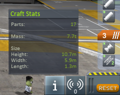
Engineer's Report
Here are some important properties: as shown, its total mass is 7.7 tons - and if we know the maximal thrust of the engine(s), the value of the maximal acceleration in g, or the TWR on the Kerbin can be easily counted (TWR ~ 2.67/7.7 = 2.68) (note: 206.7kN/g → ~20.67t) - the thrust at sea level. If we remove the propellant from the tank we can see the mass of the depleted rocket. In this case the maximal acceleration of rocket just before the depletion of resources: 21.5/3.7 = 5.81. (megj.: 215kN/g → ~21.5t) - we count with the vacuum values as it can happen at high altitudes. Well, it seems some extra pairs of boosters are needed on the tower for this case...
Well, if you feel the need to testing it, do not worry about the rest of the tutorial, you can continue after the test. This tutorial teaches by read and do method, so you ought to do it, even this test takes time.
The root part
Activate the root mode, click on the decoupler ring and then the fuel tank. As it had done the fuel tank became the root part. Clicking on the decoupler ring by the cabin piece can be removed. This method provides a good possibility for replacing the section built earlier retaining the newer section.
And the subassemblies
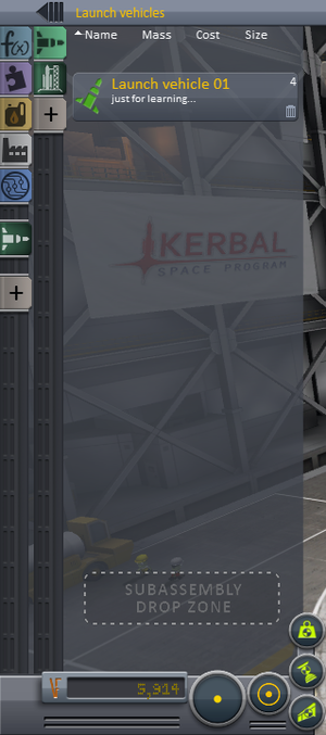
For entering the subassemblies menu has to change the Parts menu to advanced mode by clicking on the solid arrow (Enable advanced mode). Then an icon-bar rolls up where over the default Function filter we can sort Module, Resource, Manufacturer and Tech Level. Even more category can be created by clicking on the icon illustrated with a plus mark, similarly to the subassemblies menu library system. The green subassemblies icon is just above the plus mark icon. Click on it.
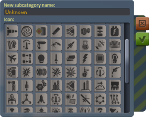
Another icon illustrated with a plus mark appears here: floating the mouse over it the appearing Add custom subcategory text shows what it is for. In the window appearing by clicking on it you can write out the New subcategory name: line and can choose a well-fitting icon for it from the icons beneath the line. If you are done, click on the green check-mark, (✓), or for leaving without saving, on the red X(✕). From now on, the newly created subcategory works as a filter-library. Right clicking on the icon of a customized category allows you to modify it, and erase it by the trash-bin icon (Delete) also confirmation is required by choosing the No or Yes (Delete) if the subcategory is not empty.
Entering into the created subcategory by clicking on its icon only the craft placed into the given subcategory remains visible - clicking on the All subasemblies icon on the top of the column makes all of them visible. For placing a subassembly into a subcategory (or into the All subassemblies) just catch the given group of parts, and drag over the rectangle titled SUBASSEMBLY DROP ZONE and release. Then you have to fill the line of Name and you can leave useful words into the window of Description for easier finding later. For exiting this window chose Cancel or Save buttons - their effects match to their titles. The ready subassembly can be deleted by clicking on the small trash-bin next to its name. There is a Remove from subcategory option (for fast moving to the All subassemblies) under the Cancel and the Delete when it is in a subcategory.
Let’s create a subcategory for the "Launch vehicles" and save our little launch rocket into it. If it finished you can try the rest of the functions too.
The typical payloads - and the common systems of the craft
The propulsion
Let’s start our lesson with a refueling unit. For the maximal efficiency - as its mission doesn't need any kerbonaut's activity - using a remote unit is a more practical choice - as an RC-001S on the picture. Well, start with the parts of the main purpose - the fuel carrying liquid fuel tanks. For the greater capacity we would need tanks of 2.5m radial size, but for docking I'd prefer the lighter normal sized (1.25m) docking port. The streamlined connection between different sized parts is possible using the proper adapters, although there are some fuel tank working same way, like the C7 Brand Adapter - 2.5m to 1.25m. The type of the engine depends on the environment and purpose, beyond the size of the craft. The launch vehicle has to be able to accelerate with 2 g - and has to work efficiently at sea level too. The middle stages need less, even 1 g can be enough if initiated at the ending phase of the gravity turn - as it used at high altitude the values belongs to vacuum can be counted. The interplanetary travels needs this level too, but for experienced players taking on the long, several round burnings, this value can be decreased to 0,2 g, or even less depending the target celestial: the slow rocket makes the encounter and proper the burn out difficult, or even impossible as a moon's orbit crosses the craft's trajectory. The propulsion of the landers mainly depends on the properties of the targeted celestial body. The surface gravity limits the minimal (and optimal) trust as it gives the numerator of the thrust-to-weight ratio. Bodies without atmosphere gives the opportunity of gravity turn with early pitching maneuver, and stale ascending trajectory - requires great thrust. The bigger thrust always makes the maneuvering of the craft more comfortable, but it can be increased at cost of the Δv (Delta-v) means range.
As this unit doesn't need great acceleration, serves mainly for circularization and minor orbital maneuvers, a light and efficient "Poodle" seems an optimal solution.
Stabilizers (SAS) and energy generators
Most of the command unit equipped with a kind of SAS unit, but the probe cores in contradiction with cabins don't generates copious amount of torque for stabilization, as a result of this dedicated reaction wheel has to be installed for this purpose. An Advanced Inline Stabilizer is the proper sized for installing in this craft. While both the probe core and the reaction wheel needs electric charge for working, more than stored in cores, batteries have to be installed too, or the control over the craft will be lost during the orbit darkness time. As the batteries play the main role, the probe core's energy can be reserved for emergency in its tweakable menu. As there are no battery going forever, and the mission can hold for a long time, some electricity generator must be installed on this stage. The solar panels worth to place on symmetry of 2x, 3x or 4x on the side for being at least one get enough light almost independently from the orientation of the craft. The deployable types produce more power, but they work on deployed state and also are more vulnerable than the simple rigid OX-STAT Photovoltaic Panels. If we cannot commit ourselves on the sunshine the nuclear generators or fuel cell would be needed, but as this stage reaches only the low Kerbin orbit for re-fueling, the expensive gadgets are not necessary.
The reaction control system (RCS) and the docking devices
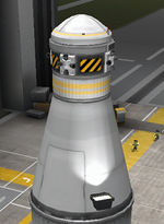
For successful docking there are three extra things are needed: docking port, reaction control system (RCS) and proper amount of monopropellant. Well, a Clamp-O-Tron Shielded Docking Port fits perfectly on the top of the unit. The monopropellant tank installed in this unit depend on at first the amount of propellant needed for docking, and at other hand amount of the desirable fuel for transfer to the targeted vessel. As you see, now an FL-R25 RCS Fuel Tank was chosen.
The rotation can be achieved sole employment of the reaction wheels, but the fine translational movement is impossible without RCS.
The Vernor Engines can be used for greater craft, working with liquid fuel-oxidizer mixture instead of monopropellant, the monopropellant tank is useless for based solely this kind of RCS thrusters.
Lamps
To use a craft in the dark - such as docking during the orbit darkness time - installation of electric lights is mainly inevitable for illuminating the docking ports. For verifying proper situation and orientation of the lamps click on the Lights On button on the tweaking menu (popping up by right-mouse-click on lamp). The tweaking menu also gives opportunity of changing the color of the emitted light. This not necessary for the docking, but can be useful for indicating the orientation of the targeted craft in the dark.
The devices for landing - landing legs, ladders
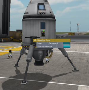
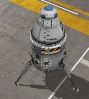
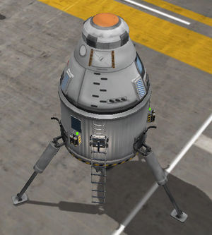
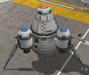
The inevitable part of the landers are the landing legs. These legs protect the craft's more vulnerable parts - as the engines - from the direct bumping to the surface. For checking if the legs extend deeper than the engine, adjust the leg's position to Start Deployed situation. Obviously, only certain types - the sorter ones - of the engines can be installed in this way. The stability at landing depend on the height of the center of mass and stride of the landing legs. The shorter construction with deeper center of mass and legs striding wider mean more stable and safer landing. The necessary number and type of legs are determined by the mass of the vessel and the surface gravity. Naturally, the legs dump the descending impulse against the solid surface, not at splashing in the see. The legs should be installed symmetrically extending under the engines, as at this case 3 pieces LT-2 legs have been installed.
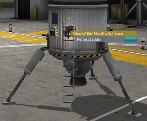
Well, another very important piece of the lander is the ladder, or want to say, mobility enhancers, enabling the kerbonauts movements between the pod and the surface. There are rigid and deployable versions of the mobility enhancers. For the lowest one worth to prefer the deployable types to reach the surface. Testing the attaining the ground is similar to learned at landing legs: right clicking on the ladder and choose the Extend Ladder option. Of course, the ladder has to be correlated to the legs. Let’s install a Telus-LV to the bottom of the lander. Let’s connect the door of the cabin and with some Pegasus I-s.
Parachutes, and everything else worth to use in the atmosphere
The parachutes can have main role during the landing, if this maneuver is executed on a celestial body with atmosphere. The number, and distribution of the types of the chutes depend on the density of atmosphere and the surface gravity beyond the mass of the landing module. In case of the pure chute descending the tolerance of the landing legs of the part touches the surface at first (attention: when splashing in water the lowered legs cannot dump the impact, so in this case the lowest part contacts the surface, what is the engine in our sample) must be higher than the terminal velocity (in m/s). Although, even employing the engines for lowering the speed at the last meters (this is the engine-assisted parachuted landing), substantially less chute is enough for the safe landing. This means weight saving solution, especially in thin atmosphere. Worth to know, the wrong use of the parachute - particularly at heavier craft - can inflict excessive stress, damaging the structure of the vessel or tearing off the chutes.
While a single chute is enough for light landing unit - as in our case the sole cabin returns, an Mk16 - drogue-chutes as the Mk25 for the heavier avoiding the damaging of the main chutes. As the attachment point has been occupied, the 3-4 pcs of Mk2-R Radial-Mount Parachutes have to be installed for main chute - and even beyond this mostly the engines have to be used for assistance. The placing of the chutes on the highest point of the craft - or at least above the center of mass - is important for the stability. The deployment altitude of the chutes is tweakable. If the craft employs drogue-chutes, lower deployment altitude can be enough - but at thin atmosphere as in Duna, worth to set them higher for the better exploitation of the braking potential of the chutes - naturally keeping an eye on the safe deployment speeds. Even some hundred (~500) meters can be enough to tweaked in the Altitude stripes for the main chutes, if the vessel braked with drogue chutes before. As the drogue chutes have to be deployed at higher speed, they has to be triggered by a separate stage before the main chutes' - and if they have to be used several times, to be collected in different action groups.
The aerobraking of the even greater vessels become even less efficient, but installation of some A.I.R.B.R.A.K.E.S increases the drag to reach better drag-to-weight ratio. The discipline is same with the chutes, installation on the top of the unit is vital for keeping the stability. The wings can be also useful for increasing the drag, and gives ability to controls the descending rate with their lift produced - but means extra weight and quite a difficult to keep stability during both descending and ascending. As most of the landers have no serious control over the descending rate, and once entered into the atmosphere the risk of overheating is high, so even very heat resistant parts, like engines cannot resist the heat, the installation a heat shield can protect the bottom of the craft, although for a single use, as the fairings protecting the rest of the vessel. So they have to fit in a separate decouple-able stage. For the heat sensitive parts a service bay can offer a proper protection. As the targeted celestials are only the moons of Kerbin, and this craft is not so big, these devices can be jilted.
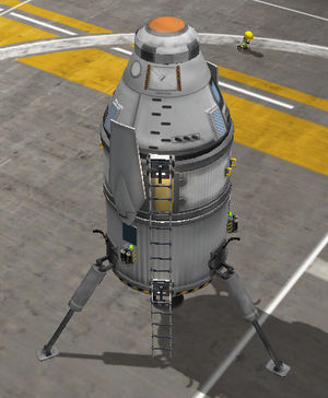
There is a lander with service bay and aerobrakes on the picture on left. It is basically a failed construction - the center of mass is high relatively to the stride of the legs. And actually the position of the aerobrakes is not ideal...
And some parts can be required
Some other optional, but highly recommended for the dark environment is the placement of the electric lights. It also helps the surveying of the surface's distance and evenness. The preferable solution from the assortment definitely is the Illuminator Mk1 due to longer range.
And some phrase about the re-usability
It is not worth to equip a lander with fuel supply for returning to Kerbin from greater distance or for several landing. It is more practical to refuel from the interplanetary carrier. One option is the intallation of a docking port on the top of the lander - and substituting the removed drogue-chutes with some Mk12-R Radial-Mount Drogue Chute. But if we use such a strong docking port like the Clamp-O-Tron Sr.l, then several celestial bodies can be visited with this single lander. But it also means the docking port takes the place of the engine. Don't panic - there is solution!
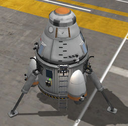
There are surface attached Mk-55 engines installed symmetrically to the lander on the left picture, while there are some LV-909s installed under the 1.25m fuel tanks (and those are fed from the big central tank). These constructions generates greater drag - meaning higher fuel consumption and worse stability for the launch vehicles - but there are several advantages too. With the removal of the central engine the legs can be placed on a higher position or replaced to the lighter LT-1 - resulting lower center of mass and increasing the stability. The engines are not stacked, so they can assist to the propulsion of the lower stage. There are some parts hard to placed in a standard hull such the SC-9001 Science Jr.s or the top mounted parachutes (see the picture) - but nacelles gives a perfect place for installation. Even the legs can be placed on these nacelles for wider striding and even more improved stability, and makes the landing possible on rather uneven surface. This make these wider constructions can be preferable for a single use missions, and compulsory for endlessly used landers on celestial bodies without atmosphere. The striding of the legs can be increased even more with pylons placed between the main hull and the nacelles. Installation of RCS on the craft is also inevitable for docking - although the reaction wheels can ensure the adjusting and maintaining the orientation, but the translation is impossible without the reactive thrusters.
The construction of launch vehicles
The launch vehicles are the stuffs capable to lift the chosen payload to the low orbit. The launch vehicle can have one or several stages - the starting stages (and boosters) used for lifting up the vessel are followed by the middle stages used to reach the circular obit. The rule is still valid: the upper stages determinate the lower.
The middle stage has to increase the speed of the craft with 1,500 m/s after leaving the dense atmosphere and turned to nearly horizontal at altitude of 30,000 m. An X200-32 can supply enough fuel for an engine optimized for the vacuum (high specific impulse at 0 atm.). The estimated mass is ~45 tons, the needed thrust is 500 kN, so the light and efficient "Poodle" with its 250 kN thrust is inadequate, so the 650 kN strong "Skipper" is the winner. Although it is heavier, but can ensure the acceleration of 1 g (~10 m/s) at the initiation of the burning. Well, this stage also has to be segregated with a decoupler. Later, as our engine is stronger than required, the remaining mass allowance can be effectively spend with the extending this stage with stacking an X200-16 in.
Most cases the interplanetary stage can act as a middle stage (supposing, its acceleration approximates the 0.5 g, or the prior stages stet only the circulization for this stage - and the player enough experienced), but in this case the propellant used for circulization must be refilled - with a refuelling unit built in the tutorial. In case of interplanetary stages the acceleration can be to sacrificed in most cases. The main principle is there is no definite margin between the roles of the certain stages, but there is definite requirements of the particular stages of the missions.
Due to the mass of the starting stages even more stabilization is needed - and as these stages works in the atmosphere this can be achieved with employment of winglets, such the AV-R8. As the efficiency and the thrust depends on the atmospheric pressure, it is recommended to count with the value belongs to 1 atm of the engine. There is only one dedicated engine of 2.5m diameter for this purpose bigger than "Skipper" to fit under the decoupler and the tank: the "Mainsail". As the desired starting acceleration of the ~2 g, 70 tons of starting weight accords to the the 1,379 kN thrust at the sea level. This allows only a single X200-32, far from the need of getting to orbit. There can be more tanks stacked, but it is not solution for each case, as results worse TWR and slower ascending at the start. Long story short: bigger fuel provision indicates worse efficiency at ascending. At this case the installation of the second X200-32 highly profitable, the third means far smaller step forward, and at the next tank reached the point when the next dose of resources cannot compensate the increase of the inefficiency. Sincerely, the middle stage gives no advantage due to the weakness of the starting stage. Yes, there is a stronger LFB KR-1x2 liquid fuel booster, but lets' forget it for the next minutes to talk out the another methods. Well, let see those to enhance this basic construction to a serviceable one.
Bigger size
The need of bigger tank and bigger engine means a bigger rocket. A bigger tank and a more powerful engine of a grater radial size can be stacked under the 2.5m part with a streamlined adapter.
Lets' fit an Kerbodyne ADTP-2-3 under the decoupler for the streamlined transition. The engine is S3 KS-25x4 withe sea level thrust of 3,476 kN, more then double of the Rockomax "Mainsail"-t. The stating weight of 174 tons abundantly covers Kerbodyne S3-14400 Tank and a Kerbodyne S3-7200 Tank, and even two Kerbodyne S3-14400 is perfect solution. Just fit some AV-R8 Winglets on the bottom for the better stability, and some TT18-A Launch Stability Enhancers to hold. This enlarged stage easily can lift the refueling unit to orbit.
Naturally, this method cannot be used infinitely - there is not always a bigger one.
Multiple engines and stacks
More thrust can be achieved not only with a bigger engine, but employing several engines too. Placing three Rockomax "Mainsail"-s in the starting stage results sharing the payload's weight among the three engines. So each engine can get three X200-32 with keeping the efficient thrust-to-weight ratio.
This method gives clumsy but usable rockets, especially if there is no other option. There are built in adapters for 1.25m stacks, splitting into 2, 3 or 4 stacks. The lower tanks of the stacks should be connected with EAS-4 Strut Connectors. For the 2.5m set install nose cones on the top of the tanks, like the Protective Rocket Nose Mk7 for decreasing the drag. The main problem with this method, only same kind of stacks - same tanks and engines can be used efficiently. Albeit there are tricks to do so. Behold:
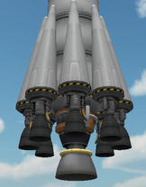 Mainsail pieced out with eight LV-T30 provides enough thrust. |
The first trick based on installation extra engines (on left), the second is the fuel-balancing of the different stacks with proper installation FTX-2 External Fuel Ducts (on right).
Boosters
The boosters are decouple-able tools increasing the thrust at the launch for a short time and mostly attached radially. Since their thrust-to-weight ratio is long sight better than the main rocket - can improve the efficiency of ascending: allows the fuel-saving by lower throttle-level or having more fuel in the main stack. There is two main type of boosters, the solid rocket booster and the liquid fuel booster. The first type invariably integrated in one part, and not reacts to the throttle level - so gives full thrust during saving the fuel of the main rocket, and fairly cheap.
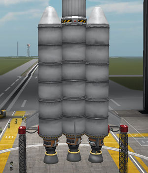
Well, lets' install three Rockomax X200-32 Fuel Tanks, and finish the stack with a "Mainsail". OK, it is a bit over the ideal weight, but now the boosters will lift the great ratio of it. Put 4 Hydraulic Detachment Manifold symmetrically on the tanks to push the boosters off the rocket. Fit S1 SRB-KD25k on each of the decouplers to help to lift this overgrown rocket to altitude of 10 kms. Listen to the greenish glowing of the touched part (on which the part would be attached) during the installation for avoiding the fitting the boosters directly on the tanks. Put Aerodynamic Nose Cones on the top of the boosters, and AV-R8 Winglets on the bottom of the rocket for better stability and TT18-A Launch Stability Enhancers for holding the rocket on the launch pad. The boosters and the stability enhancers has to be added to the starting stage, the decouplers to the next.
The liquid fuel boosters rather worth employ in fuel crossfeed construction.
Fuel crossfeed
The simplest example of the crossfeed system is the drop-tank, albeit the they are not used to employed on the launch vechiles. The drop-tanks worsen the thrust-to-weight ratio, so they can only be used when it doesn't make problem: interplanetary stages, or at landers' deceleration stage. The crossfeed systems are mainly drop-tanks equipped with reaction engine, and don't ruin the agility of the craft. Now, we will see how it works on an example. Well, let's examine how we can enhance the efficiency of the multiple stacked rocket.
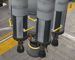
Insert TT-70 Radial Decouplers between the main and the supporting stacks, albeit the TT-70 has smaller ejection momentum, but keeps the supporting stack farer from the main rocket. For this big boosters the needed force is far higher than any decoupler could ensure, therefore some Sepratron Is have to be employed for the disposal, and somewhat like the pod equipped with LES - the Sepratrons have to be placed in same stage with the decouplers, and keep an eye on the symmetry. Now we have liquid fuel boosters have no sense as they deplete their fuel resources with the main rocket in same time. We can play with the sizes of the tanks to make a reason of the existence of the decoupler, but there is no sense of a too big rocket, and boosters with too short burning time. It is more practical, if the empty tanks would be removed with the boosters too - and this is possible with the crossfeed system. The fuel supply of the supporting rockets can be drained with FTX-2 External Fuel Duct. It is important to click on the drain tank at first and the collector at second. This method unite the need of the whole thrust at starting and the follows the journey with full tanks after the decoupling - mainly as its own middle stage. Well, as you can see on the appended picture, the ratio of the fuel tanks can be changed. Connect the stacks with EAS-4 Strut Connector for mor rigid constructions. The supporting rockets needs an aerodynamic top, like Protective Rocket Nose Mk7 for decreasing the drag - and now as the same volume is not a rule, the use of C7 Brand Adapter - 2.5m to 1.25m or its slanted version combined with a Aerodynamic Nose Cone or any kind of advanced nose cones.
This launch vehicle is able to lift more serious payloads to orbit, but there is even more refined version of this, when a booster feeds another booster.
The asparagus staging
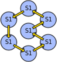
In case of the asparagus staging the boosters feed each other in line. The Kerbal X works by this way too. Lets' see how can it be constructed.
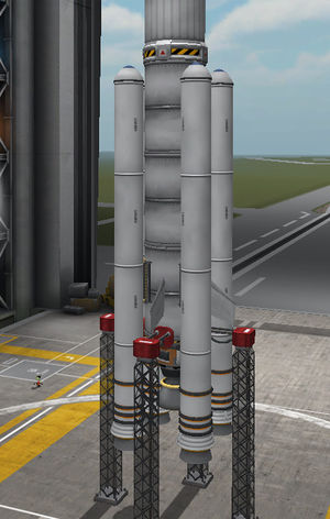
Well, switch the angle snap on, and the symmetry mode on axial-symmetry for a pretty rocket. Place a decoupler on the rocket, what is a TT-70 on the picture. This decoupler will hold the liquid fuel booster containing two FL-T800 Fuel Tank an Aerodynamic Nose Cone on the top, and LV-T30 Liquid Fuel Engine on the bottom. If you are afraid of collision between the booster and the rocket, install some Sepratron I on the boosters.
If we have done all of this, make two copy of this part (of course, the number of copies can vary). Push the mod key, and click on the decoupler. That is the way to copy the booster counted from the decoupler. Fit those pairs at 60°s. Now lead an FTX-2 External Fuel Duct from one of the pair to the next one, and from there an another fuel duct to the third. And at the last pair, lead the fuel duct to the main rocket. An naturally, finish the building with installation of the AV-R8 Winglets and the TT18-A Launch Stability Enhancers.
If the hardware is finished, the staging has to be adjusted: the staring stage - at the bottom of the bar - contains the main rocket's Mainsail and the engines of the launch stability enhancers. And now, the more difficult part of the proposition. Search the decoupler of the booster on the end of the crossfeed-chain (the most distant from the main rocket), and put into the next stage (and if the boosters have Sepratrons, put them into it too). Tne next staging slot contains the staging icons of the next booster (what the previous booster feed directly), and so on till the main rocket.
And the combination of them
And naturally all of the mentioned methods can be combined - and even this means the best solution: the enlarged stage can be improved with solid rocket boosters, or a supporting crossfeeding rocket, or even we can put drop tanks on the top of the solid fuel boosters. This game barely forces to diet the creative mind!
- If our launch vehicle is finished, saved from the middle stage as a subassembly, just place under the lander the craft for visiting the moons of Kerbin. Using the refueling unit, you can have a craft for resupply or practicing the docking with minimal effort. Have fun!
